
IO Expansion Shield For Arduino
Support RS485, Xbee (Xbee pro),Bluetooth,APC220,SD card read/write
Support RS485, Xbee (Xbee pro),Bluetooth,APC220,SD card read/write
Keywords: IO Expansion Shield For Arduino
PES025


IO Expansion Shield For Arduino
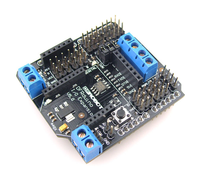
The DFRobot IO expansion board is evolving, this latest V5 IO expansion shield is now supporting Xbee. It combines our popular Xbee shield with IO expansion shield(V4). It even supports SD card which provides the ultimate functional expansion for Arduino so far. As its predecessor, it supports RS485, APC220, Bluetooth communication, servo control.
It uses an SP485CN chip to handle comms.
The screw terminals (assuming that the three jumpers are set to '485') marked 'A' and 'B' go directly to the IC 'A' and 'B' pins (6 & 7 respectively).
The screw terminal marked VCC goes to the IC VCC pin (8), and also to the board's +5V line (i.e. the Arduino's +5V rail).
The screw terminal marked GND goes to the IC GND pin (5), and also to the board's GND line (i.e. the Arduino's 0V rail).
The chip's DI (Data Input?) pin (4) is connected to the Arduino's Digital Pin 1 (TX).
The chip's RO (Data Output?) pin (1) is connected to the Arduino's Digital Pin 0 (RX), with a resistor pull-up to the +5V rail.
The chip's DE (output enable) pin (3) is connected (via a resistor) to the Arduino's Digital Pin 2 - this is active high.
This DE pin is also connected to the chip's RE bar (receiver enable) pin (2) and therefore controlled by the Arduino's Digital pin 2 too - this is active low.
Arduino Digital Pin 2 = Rx/Tx 'Enable'; High to Transmit, Low to Receive
So, to transmit data from Arduino Digital Pin 1 you need to take Digital pin 2 high, and to receive data to Arduino Digital Pin 0 you need to take Arduino Digital pin 2 low.